|
|
Post by millard1399 on Oct 31, 2008 17:32:34 GMT 10
G'day All,
I've done a fair bit of soldering of copper water pipes over the years, so I'm able to do a reasonable job of soldering stuff. However, when it comes to joint soldering of the earth wire for the van tail-lights, etc, I'm struggling a bit. I'm trying to splice into the new earth wire along its length, and solder an offshoot wire to each of the tail and clearance lights (there's no earth lead so I'm installing a complete new length around the van).
When I cut and remove a quarter inch of the plastic sheathing, and then press my small soldering iron onto the bare copper wires, the plastic nearby starts to melt before I get to the point of being able to melt the solder. Is there some trick of the trade that minimises the melting of the plastic when it's so close to the soldering iron?
Any help appreciated...
cheers,
Al.
|
|
|
|
Post by kiwijim on Oct 31, 2008 18:45:07 GMT 10
G'Day Al, the secret is to beat the perisher at it's own game, if you have a heat gun you're laughing, bare about 5-10mm of copper then use the heat gun to soften the covering back from the end for about 50mm then grab a pair of pliers, latch onto the end of the wire and pull it out of its cover while the covering is soft, do your soldering then let it cool, grab the heat gun and reheat the covering and slowly stretch the covering back up to and over the soldered joint on both sides of the joint........"wella" a completely covered and insulated joint sounds easy doesn't it ........have fun, don't burn the pinkies. ;D ;D ;D kiwijim  |
|
|
|
Post by keelz on Oct 31, 2008 19:14:39 GMT 10
Once you've bared the wire - use a solder with a flux core, you need to 'tin' the copper. Problem with old copper if the oxygen has gotten into it the copper tends to oxidise making it harder to get the solder to stick - then you end up heating the cable longer, etc. On the wire you are joining on - perhaps a apply a 'tin' coat to it also to prepare it. Then place the two together and hit with the heat to join the two solder coated wires together. Al, how many watts is the iron you are using? I use about a 25-30 watt iron for small wiring. If you're wires are heavier guage - you need to get a bigger iron because it means you can give the wires a really short burst of heat from the iron to melt and flow the solder but because you aren't 'holding it on' as long, you don't melt so much insulation. I keep about 3 irons - one 15watt, one 25watt, a one big bertha 80 watt old school iron for the bigger jobs. Sometimes i wish i had something in between - perhaps an adjustable bench type soldering iron with a dial setting would be good. Onto the patch-up situation:- Hey don't fret if you melt the insulation  - let me introduce you to my favourite product for fixin' up wires on cars, boat trailers and caravans..... it's called "Liquid electrical tape". It's like a goooey bituminous stuff in a tin with a brush. After you finished cutting, splicing and soldering and you have all these exposed bits of wiring - brush on a couple of coats of this liquid goo. It takes a few hours to dry decently but basically forms like a rubber insulation coating back around the splice/repair. After that, I just wrap a protective layer of decent grade leccy tape such as 3M electrical - which will keep it's stickiness for a long time, don't be tempted to buy the discount pack of 10 rolls at the local bargain store! I've had to patch up dodgy trailer wires and have come back to the liquid tape stuff some years later and still found it to be in really good condition despite being dunked in salt water, heat, sunlight, etc. You will find it at places like Bias boating, Whitworth Marine, perhaps some auto places. From memory about $10 for a small tin? Lasts for ages! Hope this helps  Cheers |
|
|
|
Post by atouchofglass on Nov 1, 2008 6:43:29 GMT 10
The guy that did my electrics (240V) didn't use any solder just connectors that screwed the two wires together....
Available at all electrical shops
Perhaps that is an alternate way of doing 12V as well?
I know some will deride the idea but even with soldering you get dry joins...
Cheers
Atog
|
|
|
|
Post by millard1399 on Nov 1, 2008 17:27:35 GMT 10
Ok fellas, I digested everything that you've said...and then ignored it all...  No, not by any means!! The info you guys give out is just fantastic! ;D ;D I shouted myself a new soldering iron today, one with the flat blade tip. The one I was using for yesterday's effort had a 30W pointed tip and it wasn't transferring enough heat to the wire. Today's purchase was a 40W one, so I've now got a couple of different irons to choose from. Anyhoo, today was "mad scientist" day, and working out how to do the perfect solder joint was the task. After reading what you guys said in your replies, I also did a bit of searching on the 'Net' and found some info about using a "heat sink" when soldering wires. Apparently, heat sinks are commonly recommended when soldering electronic components, so the heat from the soldering iron doesn't get to the actual component, only the end wires. Also apparently, you can buy special heat sink clips, or you can use alligator clips as a cheap but effective substitute. So today's experiment was this... I cut and prepared the wires for soldering. (The wires are from fresh spools of auto wire I bought yesterday). I clipped an alligator clip at both ends of the cut section, to act as the heat sink. Then I soldered the joint, using very thin resin (rosin) core solder which was the type recommended on the Net. This photo group shows the steps involved...  I noticed a significant reduction in the amount of 'melting' of the plastic sheathing at either end of the solder joint, due to the 'heat sink' effect from the clips. So far so good... When I was in Bunnings today, buying the new soldering iron and some other electrical bits, I came across packets of those heat shrink tubes. I thought, "Hmmm...I've got some of those in the shed, and I've got a heat gun...hmmm-hmmm." So the second part of the experiment was to cut a short length of heat shrink tubing and feed it over the soldered joint and then shrink it...  And there you have it. It doesn't look too bad to me, so if you fellas say that I can do it this way (meaning, is there anything wrong with me doing it this way  then I'll have a go at doing the proper job for the van. I'd appreciate any opinions about possible problems, etc. cheers, Al. |
|
|
|
Post by atouchofglass on Nov 1, 2008 18:59:02 GMT 10
tis a thing of beauty ;D ;D
|
|
|
|
Post by keelz on Nov 1, 2008 19:08:53 GMT 10
Looking good Atog yep there is nothing wrong with using screw connectors - the battle with a lot of them i guess is that when working with smaller guage 12v wiring and lower voltages it's hard to get a nice connection sometimes particularly with smaller guage multistrand wire that tends to pull out of bullet connectors or terminal blocks. If it's in an accessible location screw connectors or terminal blocks are great for terminating at final ends of cables - eg power to back of fridge, light fittings or accessories so you can remove for servicing. But i think for Al's application where he is intending to conceal permanent wiring in the wall frame of the van and he probably doesn't want to be removing the cladding for a long long time (correct me if i'm wrong here Al!) you really want to aim for the best connection possible. A soldered joint if done correctly will also have very little voltage drop and after many years of rough roads and touring you won't have flickering lights and earth return faults! In 240 volt most electricians do everything with screw connectors and bullet connectors, twist wires together in back of fittings, etc and terminate - it's quick and easy, plus I guess with 240v high voltage work you don't get the same level of problems with voltage drop, etc. However that said - I have in the construction industry often seen "hot" joints in the backs of circuit breaker bases, fuse holders, main switches, etc at main switchboards where a sparky has done a 'she'll be right' quick job and if the connection is not done correctly, twisted together tight and the screw is not biting down hard on all wires and there is a slight gap, it will tend to arc/spark when load is applied to the cable and heat up over time and can result in the wire melting, causing fire and tripping circuit breakers, etc. It literally fries a few cm's of the ends of the cables then you hear a loud POP!  I think the heatshrink is a good idea Al, i have to restrain myself from using too much heat  - too much heat and the sharp end of the wire might melt through and cause a short later on..... so it only takes that little bit of heat to shrink up so it won't fall off. cheers Keelz |
|
|
|
Post by millard1399 on Nov 1, 2008 20:51:25 GMT 10
Keelz, you're darn tootin' that I don't wanna be pulling this van apart ever again!! This is the one and only time I get to make it right! I've used a heavy duty double-screw through connector in one place for the 12v wiring, but I fed the connector onto one wire on one side and then twisted the two wire ends together. Then I slid the connector back over the join and screwed the two screws down onto the twisted joint. Hopefully that is as secure as it can be. The connector is then nailed into the framework to stop it moving about. For the 240v light cable wiring (1.5mm dia), I stripped the strands back far enough so I could twist the strands and then double them back on themselves before putting the looped wire into the terminal socket. If two wires then twist together and double back same. That's the equivalent of four wires twisted together which I've found is the max that can be fitted into the typical size light switch terminal socket. All of the 240v and 12v cables will be anchored to the timber frame with cable clips wherever possible, rather than just left hanging in mid air, like it was across the front and back of the van originally The other thing I've found while working on the electrics is that two of the switches (so far) had significant arc burn on the contacts inside the switch. I pulled the switches apart and filed the arc burn off to give 'new' metal-to-metal contact. One of the switches wasn't working at all before, on my test rig, and the other was giving intermittent operation of the test light. Both are now good as new. I'll be dismantling all the other switches as I go round and refurbishing the contacts in them as well. (I found it interesting that all the 240v switches and power points in this van are of the 'double pole' type, which I didn't think was available back in those years. So at least the van conforms with the latest electrical standards in that respect ;D) ...I just remembered as I'm typing this that I meant to have a look at the smoke alarms in Bunnings today, but forgot all about it  . Oh well, looks like another trip... cheers, Al. |
|
|
|
Post by millard1399 on Nov 6, 2008 19:06:43 GMT 10
I did some more joint soldering yesterday. (I know that, I was there with you! Oh, sorry...forgot I was just talking to meself...)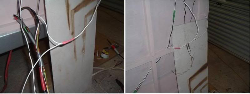 I'm convinced of the value of the alligator clamp at either end of the joint. When I took one off to try and put a bit more solder towards one end, the plastic sheating at that end instantly started to melt. But with the clips in place, very little softening of the plastic occurred. Today's handy soldering 'tip':If you have a four-month-old puppy, DON'T leave your solder cannister on the floor of the garage...  cheers, Al |
|


 - let me introduce you to my favourite product for fixin' up wires on cars, boat trailers and caravans..... it's called "Liquid electrical tape". It's like a goooey bituminous stuff in a tin with a brush.


 then I'll have a go at doing the proper job for the van.
 - too much heat and the sharp end of the wire might melt through and cause a short later on..... so it only takes that little bit of heat to shrink up so it won't fall off.
 . Oh well, looks like another trip...